Other products

ROBOTCORE Collaborative

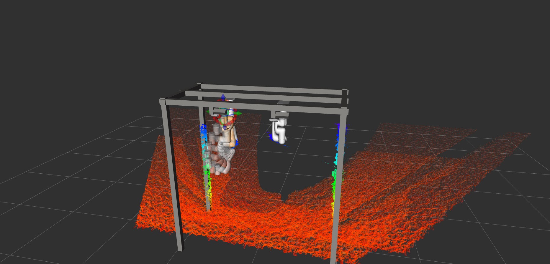
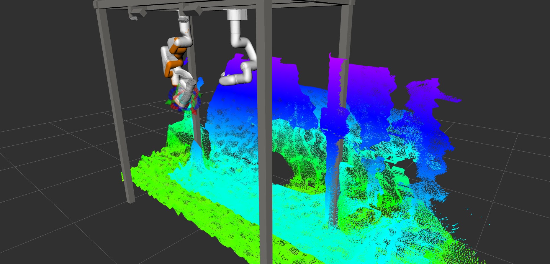
Dynamic collision avoidance:
Advanced Human-Robot Collaboration with Accelerated Adaptive Evasion

ROBOTCORE® Collaborative is an innovative Human-Robot Interaction (HRI)-centric hardware-accelerated control approach that ensures seamless and safe collaboration between robots and humans delivering dynamic collision avoidance. By leveraging robot perception and advanced FPGA technology, it provides unparalleled determinism and rapid response times, crucial for preventing collisions and aggressive behaviors in shared workspaces between humans and robots. This cutting-edge solution is fully API-compatible with the ROS 2 control stack, allowing for easy integration into existing robotic systems while significantly enhancing their collaborative capabilities.

Get ROBOTCORE® Collaborative Benchmarks
ROBOTCORE® Collaborative

Revolutionizing Human-Robot Collaboration

ROBOTCORE® Collaborative is an innovative Human Robot Interaction (HRI)-centric hardware-accelerated control approach that ensures seamless and safe collaboration between robots and humans, without collisions or aggressive behaviors. By leveraging advanced Artificial Potential Field (APF) based control for safe and efficient robotic operation on industrial scenarios and FPGA technology, it provides unparalleled determinism and rapid response times, crucial for preventing collisions and aggressive behaviors in shared workspaces between humans and robots. Moreover, this cutting-edge solution is fully API-compatible with the ROS 2 control stack, allowing for easy integration into existing robotic systems while significantly enhancing their collaborative capabilities.

With ROBOTCORE® Collaborative, industrial environments can achieve a new level of efficiency and safety in human-robot interactions. The hardware acceleration enables real-time processing of complex sensor data and instant adjustments to robot behavior, ensuring smooth and safe collaboration even in dynamic and unpredictable scenarios. This technology paves the way for more flexible, productive, and human-friendly robotic systems in various industries.

Benchmarks Talk to us

Safe, Efficient, and Intelligent
Human-Robot Collaboration

ROBOTCORE® Collaborative revolutionizes traditional robot arms, transforming them into advanced collaborative arms. Our solution offers:

Safety First

Collision-Free
Operation

Advanced algorithms ensure robots avoid collisions with humans and objects in real-time.

High Performance

Hardware-Accelerated
Control

FPGA technology delivers microsecond-level responsiveness for smooth interactions.

Interoperable

ROS 2
API-compatible

Seamlessly integrates with ROS 2 control for easy adoption. Available as an IP core or a ROS 2 package.

Multiple Cameras

Extended coverage and occlusion handling

Multiple cameras to extend the coverage of the robot environment and handle occlusions. Robot maintains its evasive behavior even when some cameras are occluded.

Unmatched Performance in HRI
Powered by FPGA-enabled Hardware Acceleration

ROBOTCORE® Collaborative sets new standards in human-robot interaction, delivering unprecedented speed and reliability. Our hardware-accelerated approach ensures consistent, deterministic behavior crucial for safe and efficient collaboration. By leveraging advanced FPGA technology, it provides unparalleled determinism and rapid response times, crucial for preventing collisions and aggressive behaviors in shared workspaces between humans and robots. This cutting-edge solution is fully API-compatible with the ROS 2 control stack, allowing for easy integration into existing robotic systems while significantly enhancing their collaborative capabilities.

Transforming
Industries

ROBOTCORE® Collaborative is revolutionizing human-robot interaction across various sectors, enabling safer and more efficient collaborative environments:

Manufacturing
Enabling robots to work alongside humans on assembly lines, enhancing productivity and safety.

Healthcare
Facilitating safe interaction between medical robots and healthcare professionals in surgical and care settings.

Warehousing and Logistics
Ensuring safe coexistence of humans and robotic systems in dynamic warehouse environments.

Research and Development
Advancing the field of human-robot interaction with cutting-edge collaborative capabilities.

Dynamic
Collision
Avoidance

The dynamic collision avoidance system offers unparalleled performance by leveraging depth camera data to detect obstacles and adjust the robot's trajectory in real-time. This system ensures lower and consistent communication latency, crucial for real-time robotic applications, and addresses major bottlenecks in robotic communications[1],[2],[3].

  1. F. Flacco, T. Kroeger, A. De Luca, and O. Khatib, ‘A Depth Space Approach for Evaluating Distance to Objects: with Application to Human-Robot Collision Avoidance’, J Intell Robot Syst, vol. 80, no. S1, pp. 7–22, Dec. 2015, doi: 10.1007/s10846-014-0146-2.
  2. F. Flacco, T. Kroger, A. De Luca, and O. Khatib, ‘A depth space approach to human-robot collision avoidance’, in 2012 IEEE International Conference on Robotics and Automation, Saint Paul, MN: IEEE, May 2012, pp. 338–345. doi: 10.1109/ICRA.2012.6225245.
  3. Flacco, Fabrizio, and Alessandro De Luca. ‘Real-Time Computation of Distance to Dynamic Obstacles With Multiple Depth Sensors’. IEEE Robotics and Automation Letters 2, no. 1 (January 2017): 56–63. https://doi.org/10.1109/LRA.2016.2535859.

Multiple Cameras for Extended Coverage. Occlusion Handling

If the Occlusion Handling (OH) variant of the control system is enabled, a Depth Grid Map is generated in the form of a file that can live either in the CPU or in the FPGA memory. The Depth Grid Map contains the mapping from one camera, the principal camera, and the other cameras introduced in the system, the secondary cameras. The principal camera's view volume is divided into a grid by dividing it into pixels (in x and y) and by a user-defined depth value in the z-axis, generating a 2.5D frustum. Each cell contains data on the pixel region and depth in which they are visible in other cameras. This mapping is then used to query the different images during the distance evaluation stage. As a result, the system can handle occlusions across cameras and provide a more accurate representation of the robot's environment, enhancing its safety and reliability while delivering the evasive behaviors required for safe human-robot collaboration.

The Control Theory Behind
Depth Image-Based Robot Control

Our system captures depth images of the robot and its surroundings, requiring calibration of the relative positions between the robot and the camera. The robot's geometry is filtered out, and critical distances from control points on the robot to the surrounding depth camera detections are identified. Control points are defined using TF frames on the robot's geometry, typically on the axes connecting the joints. These points can be added by including link elements without geometry to the robot's URDF/XACRO model. The distribution of these points should ensure the entire robot is covered within the repulsive potential field's saturation region. The distance between consecutive points should generally be less than \(\left(\frac{-3}{\alpha} + 1\right) \frac{\rho}{2}\). More points increase precision but also computation time. Based on these distances, a Cartesian repulsive vector and an attractive configuration (PID) vector are computed. These vectors are combined in joint space to obtain a velocity command. The repulsion intensity (\(v_{\text{rep}}\)) is regulated by a curve defined by \(v_{\text{max}}\), \(\rho\), \(d_{\text{min}}\), and \(\alpha\). This velocity command is limited based on joint velocity limits from other control points and smoothed through an acceleration filter before being transmitted to the robot.

The operation of this system is as follows:
  1. A stream of depth images is captured, showing the target robot and its immediate surroundings. The relative positions between the robot and the camera must be calibrated.
  2. The robot's geometry is filtered out from these images.
  3. The filtered image is analyzed to identify critical distances from control points defined on the robot's geometry to the detections from the surrounding depth camera. An example of these control points for a UR10e robot can be seen in the following image. These control points are defined using TF frames located on the robot's geometry, typically on the axes connecting the joints. These points can be simply defined by adding a series of `link` elements without associated geometry to the robot's URDF/XACRO model. The process of adding/modifying these control points to the configuration of the various involved nodes and the controller will be reflected in the documentation provided with the solution code. The distribution of these points along the robot's geometry should generally be sufficient to ensure that the entire volume of the robot is covered within the saturation region of the repulsive potential field function. This function appears in the next step, but as a rule of thumb, the distance between consecutive points should generally be less than \(\left(\frac{-3}{\alpha} + 1\right) \frac{\rho}{2}\). It is worth noting that the greater the number and density of these points, the more precise the coverage of the geometry at the cost of increased computation time.
  4. Based on these distances for the end effector control point, a Cartesian repulsive vector is computed, and based on the current goal, an attractive configuration (PID) vector is also computed. These vectors are combined in joint space to obtain a velocity command. The intensity of the repulsion (\(v_{\text{rep}}\)) is regulated by a curve defined by the attached image: Where \(v_{\text{max}}\) is the maximum Cartesian repulsion velocity, \(\rho\) is the radius around a control point where obstacles are considered, \(d_{\text{min}}\) is the minimum distance from the control point to the obstacle, and \(\alpha\) is a shape factor that regulates the slope of the curve.
  5. This velocity command is then limited based on velocity limits for each joint computed from the other control points.
  6. The joint command limited to these new limits is smoothed through an acceleration filter.
  7. This smoothed command is transmitted to the robot.

Benchmarks

(plots are interactive)

REAL-TIME DISTANCE
CALCULATION COMPUTE TIME

(in ms)

ROBOTCORE® Collaborative @ CPU
(AMD Ryzen 5 PRO 4650G)

1112.3125 ms
(min: 6.6072, mean: 41.2398)

ROBOTCORE® Collaborative @ FPGA
(AMD Zynq™ UltraScale+™ MPSoC EV (XCK26). Programmable logic running at 156MHz. Other fmax values may lead to better results.)

37.7234 ms
(min: 9.2831, mean: 16.0414)

Speedup ratio CPU/FPGA

29.49x
(min: 0.71x, mean: 2.57x)

REAL-TIME CONTROL FREQUENCY

(in Hz)

ROBOTCORE® Collaborative @ CPU
(AMD Ryzen 5 PRO 4650G)

0.899 Hz
(min: 151.34, mean: 24.24)

ROBOTCORE® Collaborative @ FPGA
(AMD Zynq™ UltraScale+™ MPSoC EV (XCK26). Programmable logic running at 156MHz. Other fmax values may lead to better results.)

26.51 Hz
(min: 107.73, mean: 62.34)

Do you have any questions?

Get in touch with our team.

Let's talk Case studies